Abstract: With the continuous development and progress of science and technology, the electricity consumption in large public places is also increasing day by day. How to manage electricity consumption more conveniently and ensure the safe and stable operation of the power grid is very worthy of attention. At the same time, the intelligent control of the circuit is also increasing. Become an important aspect of intelligent control. Transformer-distribution room automation control is a measure to improve the safety, reliability and stability of the power distribution room, reduce the cost of operation and maintenance, improve economic efficiency, and provide users with high-quality electrical energy services. Intelligent circuit control can achieve various The combination of controls to meet the needs of different occasions. This article is based on Acrel-3000 power monitoring software and ACR320ELK network power meter, ARTU-J16 control unit monitoring and intelligent management system, a brief introduction to configuration software in the distribution room power management and circuit intelligent control applications. The system has designed and implemented a decentralized acquisition and centralized control management, which realizes the unmanned management function of the microcomputer in the power distribution room, eliminating the cumbersome on-site operation of circuit breakers and improving the power supply quality and management level. Concise and practical, less investment and other advantages.
Regorafenib is an orally bioavailable small molecule with potential antiangiogenic and antineoplastic activities. Regorafenib binds to and inhibits vascular endothelial growth factor receptors (VEGFRs) 2 and 3, and Ret, Kit, PDGFR and Raf kinases, which may result in the inhibition of tumor angiogenesis and tumor cell proliferation. VEGFRs are receptor tyrosine kinases that play important roles in tumor angiogenesis; the receptor tyrosine kinases RET, KIT, and PDGFR, and the serine/threonine-specific Raf kinase are involved in tumor cell signaling.
Regorafenib is an oral multi-kinase inhibitor that is used in the therapy of refractory metastatic colorectal cancer, hepatocellular carcinoma and gastrointestinal stromal tumor. Regorafenib has been associated with frequent serum aminotransferase elevations during therapy and with rare, but sometimes severe and even fatal instances of clinically apparent liver injury. Regorafenib; 755037-03-7; BAY 73-4506; Stivarga; 4-(4-(3-(4-Chloro-3-(Trifluoromethyl)Phenyl)Ureido)-3-Fluorophenoxy)-N-Methylpicolinamide; Regorafenibum; Â Shandong Haohong Biotechnology Co., Ltd. , https://www.haohongpharma.com
Keywords: power monitoring software power meter power management
The project consists of a power distribution room, a generator room, a total of two power distribution rooms and a site lighting control room, providing office space, lighting, lighting for stadiums, electricity for air-conditioning, and other electricity. All loops are equipped with ACR320ELK network power meters, which can measure the voltage, current, power and other electrical parameters of the power distribution room. At the same time, remote switching of the loops can be realized through the electrical operation mechanism. According to customer's requirements, the designed Acrel-3000 power monitoring system can not only achieve remote monitoring and centralized management of each distribution circuit, but also realize remote opening and closing operation; and can realize intelligent classification control of site lighting according to different competition specifications. .
System analysis
The monitoring scope of this monitoring system: Before the start of the project, Party A shall provide a system diagram, a plan, and a secondary system diagram of the distribution system for the reference of the design of the second party. Party B completes the design of the system according to the actual needs of Party A and the functions of the intelligent components. The main functions are: display of a main wiring diagram interface; remote parameter measurement of electric parameters and over-limit alarm of electric parameters; remote-switching status, opening alarm, and open circuit breaker Remote switch-off and closing control of the device (this function requires that the on-site circuit breaker is equipped with an electric operation mechanism); event record, power management report (generate daily, monthly and annual reports, etc.); abnormal operation monitoring of the system; fault alarm and operation record; Report query and printing; system load real-time, history curve, user rights management and other main functions, the actual refinement of function B can modify feasibility according to Party A's usage habits and needs.
The entire system adopts a network distributed structure. The monitoring host is located in the power distribution room. In addition, each meter of the generator room is also connected to the entire monitoring system through a twisted pair cable. A total of 120 ACR320ELK network power meters are installed in the power distribution room power distribution cabinet. Multiple loops. The system adopts an open communication protocol and is connected with the distribution system through a field bus to realize data communication and control functions.
System structure
The system adopts a layered distributed computer network structure, namely, a bay layer, a communication layer and a station control layer as shown in the following figure: 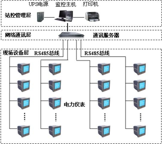
The main equipment in the compartment is: multi-function network power meter, switch, analog acquisition module and intelligent circuit breaker. These devices are corresponding to the corresponding primary equipment installed in the electrical cabinet, these devices are used RS485 communication interface, through the scene MODBUS bus networking communications, data acquisition on the spot.
The middle tier is mainly a communication server. Its main function is to collect the scattered data at the site collection device and transmit it to the station control layer at the same time. The data exchange between the field layer and the station control layer is completed.
Station control layer: equipped with high-performance industrial computers, monitors, UPS power supplies, printers, alarm buzzer and other equipment. The monitoring system is installed on the computer to collect and display the operating status of the equipment in the field and displays it to the user in the form of human-computer interaction. At the same time, the user can send commands to the field device through the system software to realize the remote control function.
The above network instruments all adopt RS485 interface and MODBUS-RTU communication protocol. RS485 adopts shielded wire transmission. Generally, two wires are used for connection. The connection is simple and convenient. The communication interface is half-duplex communication, that is, both parties can receive and send data. Only data can be sent or received at the same time. The maximum data transmission rate is 10Mbps. The RS-485 interface is a combination of balanced drivers and differential receivers. It has enhanced noise immunity and allows up to 32 devices to be connected on the bus. The maximum transmission distance is 1.2 km.
The main function of the system
First, data acquisition and processing
Data acquisition is the basis of power distribution monitoring. The signals that need to be collected include: three-phase voltage U, three-phase current I, frequency Hz, active power P, reactive power Q, electrical degree EPI, and switch quantity.
Data processing is mainly to display the electrical parameters collected according to requirements in real time and accurately to the user, so as to meet the requirements of automation and intelligence of the power distribution monitoring. At the same time, the collected data is stored in the database for user query.
Second, human-computer interaction
The power monitoring system provides a simple, user-friendly, and user-friendly interface. The main electrical wiring diagram of the low-voltage power distribution system is displayed in full English, showing the equipment status of the distribution system and the corresponding real-time operating parameters, the screen timing switching, the real-time dynamic refresh of the screen, and the analog display. 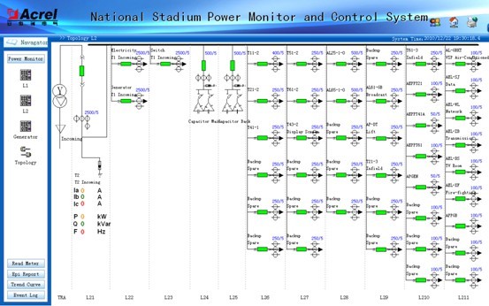
The site lighting and lighting control system meets the physical characteristics of the lighting and lighting according to the requirements of the design institute, and realizes the mode switching and control of different competition requirements through the intelligent script program, which not only meets the design requirements, but also can effectively extend the intelligent script that combines the physical properties of the lighting. The service life of the equipment. 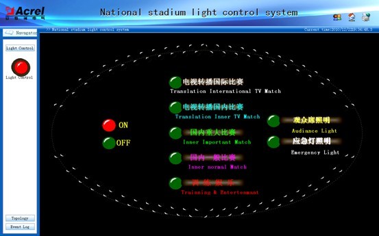
When an operational failure occurs in the power distribution system, an audible and visual alarm will be promptly issued to prompt the user to respond to the fault circuit in a timely manner. At the same time, the time and place of the event will be automatically recorded so as to be queried by the user to recall the cause of the fault.
IV. Energy Cost Management
Automatically perform daily, monthly, and annual energy statistics to achieve energy statistics, and generate daily, monthly, and annual reports.
Fifth, user rights management
The number of users who can add and remove software according to Party A's requirements and set the user's rights. For different levels of users, different permission groups are set to prevent the losses caused by human misoperation to production and life, and to realize the safe and reliable operation of the distribution system.
Sixth, the operating load curve
Timely acquisition of incoming line and important loop current load parameters, automatic generation of operating load trend curve, user-friendly to understand the equipment operating load status, real-time display of important circuit current, power data, and query history current, power data. 
Voltage upper limit setting: It can set the upper limit for high-voltage incoming voltage, low-voltage phase voltage and line voltage respectively. When the real-time data exceeds the upper limit, the data turns black into red, and records are left in real-time alarm and historical alarm.
Load limit setting: It can set the upper limit for high-voltage incoming load and each transformer load. When the real-time data exceeds the upper limit, the data turns black to red, and records are left in real-time alarm and historical alarm. Pictured 
System Features
The communication line contacts are few, the screen display is intuitive, the data is refreshed quickly, and the operating status of the field device is responded in a timely manner. Simultaneously, the system operation is simple and user-friendly. Various functions can be flexibly changed according to the user's needs. The design of the system is quick and easy, and the software is also modified. Not cumbersome.
Conclusion
This article describes the characteristics, structure and function of the stadium's integrated automation control system. This system is a part of a huge system project. To realize the automatic control function of the stadium power monitoring, there are many technical problems that need to be tackled. The author believes that in the not too distant period, the management of the convenient venue automation control system will surely have Further development.
references
[1] Ren Chengcheng and Zhou Zhong eds. Principle and Application Guide for Power Electronic Measurement Digital Instrument China Electric Power Press, 2004.4
[2] Analysis of Zhu Liquan's intelligent management system for power distribution system Intelligent Building Electrical Technology, Vol. 1, No. 4, 2007
[3] Wang Zhensheng Analyzes "Computerized Monitoring System of Substations and Substations" Intelligent Building Electrical Technology. 2006 Vol. 5 No. 3