Roasting Furnace,Energy Saving Machine,Investment Casting Roaster,Investment Casting Machine Dongying Dosun Mechanical Automation Co.,LTD , https://www.dosunmachinery.com
A working principle of the tester The working principle of the laser diffraction grating tester is shown in Figure 1. The hardware of the tester consists of four parts: the driving circuit of the laser diode, the small signal sampling and amplifying circuit, the LED display circuit and the minimum peripheral circuit of the single-chip microcomputer. The system displays a selection of two 4-bit LEDs. The dynamic scan method is used to display the light intensity ratio and transmittance of the grating in one block. 
Test principle: The laser diode drive circuit provides a stable and appropriate voltage and current for the laser diode to drive the laser diode to emit light normally. The photodetector converts the light spots diffracted by the grating into weak currents, and the current is sampled and amplified by a current circuit to obtain a voltage that conforms to the A/D sampling range. After the voltage is converted by A/D, a corresponding digital signal is obtained, the digital signal is subjected to data processing, the brightness ratio of the spot and the value of the transmittance are calculated, and finally displayed by the LED. At the same time, control buttons such as restart, clear, start/hold, and alarm zone value setting are set to match the test.
2 system hardware design 2.1 SPCE061A microcontroller minimum peripheral circuit tester MCU using high-performance 16-bit SPCE061A microcontroller, it has 7-channel 10-bit voltage analog-to-digital converter (ADC) and 32 programmable I / O port, can be In-circuit debugging through built-in online simulation circuit ICE (In-Circuit Emulator) interface. The development of SPCE061A is achieved through the in-circuit debugger PROBE. It is both a programmer (program writer) and a real-time in-circuit debugger. It can be used to replace the commonly used software tools in the development of SCM applications - hardware online real-time simulator and programmer. The 10-bit single-ended ADC converts the linear voltage between GND and VREF into 2n different digital quantities, ie, 1LSB=VREF/2n. In this system, 1LSB=2.5V/1024=2.4mV. For example, assuming that the current from the photodetector is 0.100mA and the voltage is 1V after sampling with a 10kΩ resistor, the A/D conversion accuracy is 2.4/1×100%=0.24%. Considering the current-voltage conversion error, AD sampling error, etc., the final accuracy of the test can reach 2%, which can basically meet the test accuracy.
2.2 Laser Diode Drive Circuit Design The laser diode model is SDL6161RL from Sony Corporation of Japan. The operating parameters are: the output wavelength is 650nm, the operating voltage is DC5V, the threshold current is 55mA, the operating current is 65mA, and the exit pupil power is 7mw. Laser diode drive circuit shown in Figure 2. 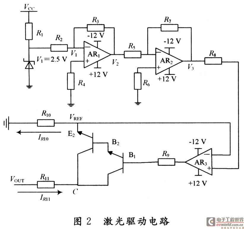
Figure 2 in the regulator tube using TL431, resulting in 2.5V regulator, after the voltage follower AR1, voltage regulator AR2 to get a stable voltage VREF sent to the positive input of AR3. The current signal from the AR3 is amplified by the Darlington tube to generate a large enough drive current to achieve the operating current demand of the laser diode. In the figure, R2 = R3, and AR3 operates in a deep negative feedback state. From the concept of virtual short, the voltages at the positive input and negative input of AR3 are equal, that is:
Since the first stage of the Darlington's operation is in saturation, the desired output voltage and current can be obtained as long as the appropriate R6, R7, R10, and R11 are given.
2.3 Small Signal Sampling and Amplifying Circuit The system has two sampling channels, one sampling 0 spot and the laser directly illuminates the detector signal when no grating is added, and the other sample the photoelectric conversion signal of the first spot. The weak current signal from the light detector is 0.01 to 0.5mA, and the ADC conversion range of the microcontroller is 0 to 2.5V. In order to improve the accuracy of A/D conversion, current-voltage conversion of the current signal must be performed and the signal amplified.
In general, the ADC converter minimizes the conversion error around the middle value of the range. Therefore, all current signals are converted into a voltage signal of about 1V at design time. The parameters that the system needs to test are the spot brightness ratio and the grating transmittance. Therefore, it is necessary to measure the current of the probe before the non-grating and the current generated by the two bright spots after the grating is added. The current before the addition of the grating is approximately 0.4 to 0.5 mA, the current of the class 0 spot is approximately 0.1 to 0.2 mA, and the current of the class 1 spot is approximately 0.01 to 0.05 mA. Magnifications can vary greatly. Among them, the photodetector for measuring the zero-order light spot and the laser light without the grating is the same. In order to make the voltage generated by both of them to be around 1V, a single-pole, double-throw switch is designed to achieve different magnifications.
3 tester software design tester main program flow chart shown in Figure 3. These include A/D conversion subroutines, LED display subroutines, and external key interruption routines. 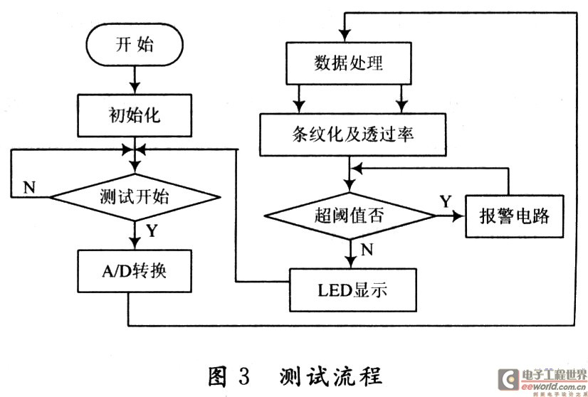
Two-way A/D is used to sample the voltage signals obtained by the zero-level and first-level spot conversions. In order to improve the stability and reliability of the sampled data, digital filtering is used. Each channel data was sampled 150 times. After removing the maximum and minimum values, they were averaged. For each qualified grating, its spot brightness ratio and transmittance value are within a certain range. If it exceeds this range, the grating parameter is unqualified, and the instrument will display U or inverted U to indicate whether the parameter is overflow or underflow. Spill, convenient for users.
4 Test results and analysis For the 10 grating samples, the brightness ratio data of Class 1 and Class 0 tested are shown in Table 1. Five sets of data were measured for each of the same samples. The reference value is the standard sample value provided by the grating manufacturer. 
In equation (5) and equation (6): δ is the relative error; D is the mean square error; Ri is the measured value; R is the average value; N is the number of terms. The test results show that the tester's test error is less than 2%, and the mean square error is less than 2.2×10⁻³, which fully meets the design requirements.
5 Conclusion The design of the use of high-performance 16-bit SPCE061A microcontroller to achieve DVD and other equipment with laser diode diffraction grating tester, very suitable for small batch diffraction grating test. After actual test and verification, it has high stability and accuracy. With overflow alarm function, at the same time, the instrument is low in cost, small in size, high in detection efficiency, and has high promotion value.
Design of laser diffraction grating tester based on SPCE061A
Introduction Laser diffraction gratings are a key part of laser read-write heads in computer disc drives and consumer electronics devices. At present, the instruments used to measure the parameters of laser diffraction gratings are still relatively rare. The laser wavelength used in the DVD read/write head is usually 650nm. This design uses a 650nm laser diode LD (Laser Diode) as a diffraction grating source, and combines a high-performance 16-bit SPCE061A single-chip microcomputer to design a laser diffraction grating tester that mainly tests diffraction gratings. Class 0 and class 1 spot brightness and grating transmittance improve the accuracy and efficiency of diffraction grating quality testing.