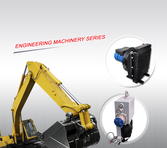
Aluminum plate&bar heat exchangers (air cooler, oil cooler, aluminum oil coolers,water cooler and combi coolers) have been widely applied
in all kinds of engineering machineries including concrete blender, concrete pump, crane, drilling Machinery,excavator,
loader, road roller etc.
Advantage:
Compact, Lightweight, High Efficient Heat Transfer
Application:
Concrete Blender Cooler
Concrete Pump Cooler
Crane Cooler
Drilling Machinery Cooler
Excavator Cooler
Loader Cooler
Road Roller Cooler
More
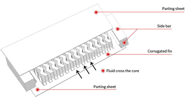
Material&Structure: Aluminum Plate-bar
Core : High strength, high heat conductivity,high safety coefficient.
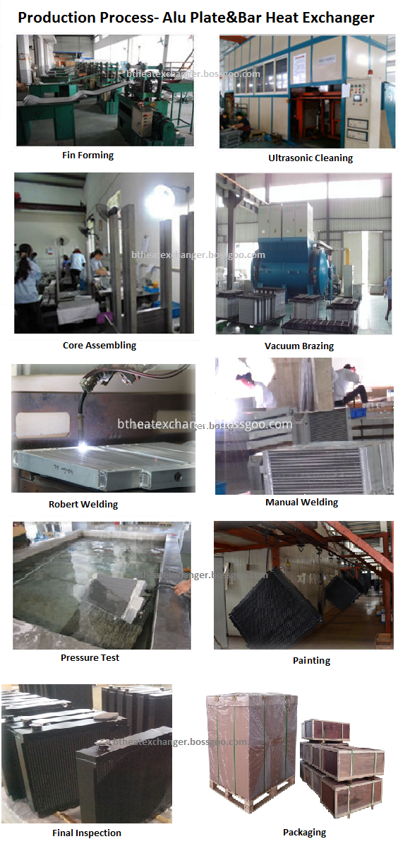
Supersonic Cleaning: High efficiency,little corrosion to metal , few pollution.
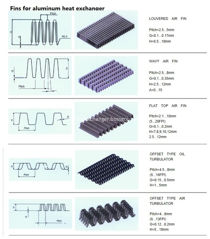
Fins: offset fin, straight fin, perforated fin, louvered fin, corrugated fin
FAQ
Q1:Could you customize oil cooler/heat exchanger?
We can manufacture plate-fin heat exchanger/oil cooler /intercooler according to your drawings or samples or parameter requirement.
Q2: I want to buy your products, how can I pay?
A :You can pay via T/T
Q3: How can you guarantee the quality?
A: One year's warranty against B/L date.
Q4: If we don`t find what we want on your website, what should we do?
A: You can email us the descriptions and pictures of the products you need, We will check whether we can make it.
Q5: Can we buy samples of each item for quality testing?
A: Yes, we understand quality test is important and we are glad to send the sample for quality testing.
Q6: What is the lead time?
A: Normal : Plate-fin heat exchanger for 2~3 weeks; Tube&fin or stacked layer coolers for 5 weeks. Exact time upon negotiation .
Aluminum Plate-Bar Heat Exchanger,Industrial Oil Coolers,Construction Machinery Cooler,Hydraulic Oil Cooler,Aluminum Oil Coolers Wuxi Better Technology Co., Ltd , https://www.btheatexchanger.com
Advantages of this paragraph 1 Screw air compressor has the advantages of high stability, high efficiency, low vibration and low noise. Screw Air Compressor
2 The yin and yang rotor and the cooperation between the rotor and the casing are set, so that the gas has less backflow leakage and no residual gap volume, so the efficiency is high. 3 The injected lubricant has sealing, cooling and lubrication. 4 Parts are few, no suction, exhaust valve plate. 1, the host: European and American brands, excellent performance, reliable operation. 2. Motor: Class F air-cooled motor efficiency exceeds EFFL standard. 3. Transmission system: The motor drive end is applied with compressor oil lubrication, high efficiency, maintenance-free and extremely high reliability. 4. Fan: The cooling air volume is large and the noise is low. 5. Heat dissipation system: It adopts plate-fin structure and high-quality materials to ensure the pressure resistance of the cooler, high heat dissipation efficiency and good corrosion resistance. 6, air filter: heavy-duty, multi-stage air inlet filter, dust removal accuracy of 1um (98% is filtered), large contact surface, long service life. 7. Oil/Gas Separator: The new generation of separators uses a new filter material that is more efficient and has an air content of less than 2 ppm. 8. Intelligent controller: All operations and related data of air compressor operation are displayed on the control panel, and it is easy and convenient to control between your fingers. High-performance, high-efficiency air compressor equipment-screw air compressors use high-capacity compression components with low rotor outer speed and optimum oil injection for high efficiency and high reliability. CompAir's latest design ensures extremely low system temperatures and compressed air temperatures. Ensure that all components achieve optimum cooling and maximum service life. Maintenance-free, highly reliable and efficient drive concept Air compressor equipment - The screw air compressor drives the compression assembly at the optimum speed for the application through an efficient drive system. No maintenance is required during normal operation. Maintenance costs Low-pressure press equipment - The original compressor design of the screw air compressor saves unnecessary maintenance costs. All components are designed for long life, with large inlet filters, oil filters and fine separators to ensure optimum compressed air quality. All oil filters and separator units of all models up to 22 kW (30 hp) are centrifugally opened and closed, reducing maintenance time. The “Speedup Service Point†allows maintenance work to be completed in minutes, with reduced downtime and maintenance costs. Built-in intelligent control to reduce operating costs, sophisticated operational control is essential. All CompAir rotary screw compressors are equipped with an intelligent control system and the control menu is easy to use. Third, air compressor equipment - screw air compressor standard L series new products - speed compressor Compiler LSR series compressor is a new product outside the standard L series products, using a unique reluctance switch variable speed drive system. This drive system allows the output of the compressor to be matched to different requirements, thus saving energy. The standard L series compressor equipment is equipped with an LSR compressor, so that the entire system output can be precisely matched with the demand, and the energy consumption of the compressor is just right. IV. Air Compressor Equipment - Screw Air Compressor Standard L Series New Product LF Aircenter, Integrated Compressor and Dryer Series This new screw air compressor series is designed to provide customers with a small, ready-to-operate The Aircentre package is small, easy to install, easy to transport and easy to handle, and is available in standard size doorways. The LF Aircentre series of compressed air is single-connected and the power supply is easy to connect. There is also an integrated dryer with energy-saving thermal mass unit. The new compressor and dryer unit is the L-Series rotary screw. The compressor is combined with a refrigerated dryer. The new LF Aircentre range is available in five models ranging from L07F to L22F (7.5kW to 22kW). The dryer unit is matched to the compressor and the output air can be dried to a constant pressure dew point of 3oC without the need for a refrigeration control valve to avoid repeated adjustments. Under the premise of ensuring air quality and dryer reliability, once the dew point is reached, the dryer unit is turned off, and the supply of large air filters that are easy to replace is used in conjunction with the dehumidifier at the inlet to ensure optimum performance. performance. The LF Aircentre range offers a wide range of outputs including 7.5 kW, 11 kW, 15 kW, 18.5 kW and 22 kW, which can produce up to 3.46 m3/min at 7.5 bar, while the highest equipment is only 1450 mm.
Edit this paragraph compression principle (1) Intake process: the motor drives the rotor, the space of the main and slave rotors is turned to the opening of the intake end wall, the space is large, the outside air is filled therein, when the intake side of the rotor When the end face is turned away from the air inlet of the casing, the air between the tooth grooves is closed between the main and the slave rotor and the casing to complete the suction process. (2) Compression process: At the end of inhalation, the closed volume formed by the main and slave rotor peaks and the casing decreases as the rotor angle changes, and moves in a spiral shape, which is the “compression processâ€. (3) Compressed gas and fuel injection process: During the conveying process, the volume is continuously reduced, the gas is continuously compressed, the pressure is increased, the temperature is raised, and at the same time, the lubrication which becomes misty due to the difference in air pressure is injected into the compression chamber, thereby Achieve compression, reduce temperature sealing and lubrication. (4) Exhaust process: When the closed tooth peak of the rotor rotates to meet the exhaust port of the casing, the compressed air begins to discharge until the matching surface of the tooth peak and the groove moves to the exhaust end face, at this time the groove The space is zero, that is, the exhaust process is completed. At the same time, the other pair of teeth of the main and slave rotors have been rotated to the intake end to form a maximum space, and the inhalation process is started, thereby starting a new compression cycle.
Edit this paragraph work pressure pressure unit has many representations. Here we mainly introduce the pressure indication unit commonly used in screw air compressors; 1 working pressure, domestic users often call exhaust pressure. Working pressure refers to the highest pressure of the air discharged from the air compressor; 2 Common working pressure units are: bar or Mpa, 1 bar = 0.1 Mpa; 3 General, the user usually refers to the pressure unit: Kg (kg), 1 bar = 1 Kg.
Edit this section volume capacity 1 volume flow, domestic users often called the displacement. The volumetric flow rate refers to the amount of gas discharged per unit time of the air compressor under the required exhaust pressure, which is converted into the intake state. 2 The volume flow unit is: m3/min (cubic/min) or L/min (liter/min), 1m3 (cubic) = 1000L (liter); 3 General, common flow units are: m3/min (cubic/ Minutes); 4 Volumetric flow is also known as displacement or nameplate flow in China.
Edit the power of the air compressor in this paragraph 1 General, the power of the air compressor refers to the nameplate power of the matching drive motor or diesel engine; 2 The unit of power is: KW (kilowatt) or HP (pound/horsepower), 1KW ≈ 1.333HP.
Edit this paragraph Use and maintenance safety precautions 1. Operation, repair and maintenance of the compressor must be carried out by qualified personnel. 2. The compressor cannot be reversed. After initial start-up or maintenance of the electronic control system, it must first be confirmed whether the direction of rotation of the motor is consistent with the specified direction before the compressor is started. 3. When removing high temperature components, it must be done after the temperature has cooled to ambient temperature. 4. It is recommended to use special oil for screw compressors. Different grades of lubricants are not allowed to be mixed. 5. Without the permission of the manufacturer, do not make any changes to the compressor that affect safety, reliability or add any equipment. 6. The original spare parts of the compressor are specially designed and manufactured. It is recommended to use authentic spare parts to ensure the reliability and safety of the compressor. 7. It is absolutely not allowed to block the compressor suction port during operation. 8. Compressed air is never allowed to breathe unless it is indicated that it can be used for breathing. 9. The compressor cannot be operated above the specified pressure and the specified temperature. 10. Once the compressor is found to be working abnormally, stop the compressor immediately and eliminate the abnormality in time. 11. Maintain and repair the compressor with the correct tools. 12. After repair, before starting, confirm that all safety devices have been reinstalled and the tools have been removed from the compressor.
Maintenance 1. Check the oil level, exhaust temperature and exhaust pressure daily to check for abnormal sounds. 2. Turn on the separator drain valve to discharge condensate before starting each week, check for leaks everywhere, check the safety valve. Check the belt wear condition (visual inspection); 3. Regularly check the intake control valve, minimum pressure valve, electric control box connection line terminal, safety valve, cooling fan; 4. Regularly clean, clean the cooler, test the reliability of the safety valve; Regularly change the oil filter core, oil separator filter, air intake filter element and lubricant.
Common troubleshooting 1. The machine does not start: check the main switch and power cord, check the motor; 2. The machine does not load after starting: adjust the pressure switch setting value or replace the pressure switch, check or replace the solenoid valve; 3. The compressor does not unload Safety valve relief: adjust the pressure switch setting value or replace the pressure switch, check or replace the solenoid valve; 4. Excessive fuel consumption: press the recommended oil, lower the oil level to the normal position, remove the oil return line to clean, replace the oil and gas separation Filter element; 5. Exhaust pressure is lower than the specified value: reduce the gas consumption or increase the compressor, check the system leakage, clean or replace the air filter core, replace the oil separator filter, check or replace the solenoid valve, check the intake control Valve, change belt, adjust pressure switch setting value; 6. Compressor high temperature protection shutdown: improve environmental ventilation conditions, clean or clean the cooler, add oil to the specified position, replace the oil filter; 7. compressor unloading operation, row The gas pressure is still rising slowly, and the safety valve is vented: check or replace the solenoid valve, check the intake control valve, and repair the unloading pipe; 8. Safety valve bleed : Repair or replace the safety valve, overhaul the minimum pressure valve, replace the oil separator filter, repair or replace the pressure switch, check the intake control valve or solenoid valve.
The air filter of the air intake filter is a component that filters out dust and dirt from the air. The filtered clean air enters the compression chamber of the screw rotor for compression. The particles inside the screw machine are only allowed to filter out within 15u. If the air filter plug is damaged, a large amount of particles larger than 15u enter the screw machine, which not only greatly shortens the service life of the oil filter and the oil separation core, but also causes a large amount of particles to directly enter the bearing cavity, accelerating the bearing wear and increasing the rotor clearance. The compression efficiency is reduced, and even the rotor is bitten and dead.
After replacing the oil filter for the first time, the oil machine should be replaced after 500 hours of operation. Use a special wrench to remove the oil filter. It is best to add the screw oil before the new filter element is installed. The filter element is screwed back to the oil filter seat with both hands. Tighten hard. It is recommended to replace the new filter element every 1500-2000 hours. It is best to replace the oil filter element when changing the oil. When the environment is bad, the replacement cycle should be shortened. It is forbidden to use the oil filter element for a long period of time. Otherwise, the filter element is severely blocked, the pressure difference exceeds the limit of the bypass valve, and the bypass valve is automatically opened. A large amount of dirt and particles will directly enter the screw main unit, causing serious consequences. The replacement of diesel engine oil filter and diesel filter core of diesel engine screw machine should be carried out in accordance with the maintenance requirements of diesel engine. The replacement method is similar to that of screw oil core.
Maintenance of oil fine separator The oil separator is a component that separates the screw oil from the compressed air [1] gas. Under normal operation, the service life of the oil separator is about 3,000 hours, but the quality and air of the oil The filtration accuracy has a huge impact on its longevity. It can be seen that in the harsh environment, the maintenance and replacement cycle of the air filter must be shortened, and even the front air filter should be considered. The oil fine separator must be replaced after expiration or before and after the pressure difference exceeds 0.12 MPa. Otherwise, the motor will be overloaded and the oil separator will break the oil. Replacement method: Remove the control pipe joints installed on the oil and gas tank cover. Remove the oil return pipe from the oil and gas tank cover into the oil and gas tank, and remove the upper bolts of the oil and gas tank. Remove the upper lid of the oil and gas tank and take out the oil. Remove the asbestos pad and dirt adhering to the upper cover. Install a new oil separator, pay attention to the asbestos pad must be stapled, the asbestos pad must be placed neatly when pressed, otherwise it will cause the pad. Replace the upper cover, return pipe, and control tubes as they are, and check for leaks.
Maintenance and replacement of screw oil has a decisive influence on the performance of the oil-injected screw machine. Good oil has good oxidation stability, rapid separation, good foaming, high viscosity and good corrosion resistance. Therefore, the user must Use pure company-specific screw oil. The new oil replacement was carried out 500 hours after the new machine running-in period, and the new oil was replaced every 2000 hours after the operation. It is best to change the oil filter at the same time when changing oil. Use shortened replacement cycles in harsh environments. Replacement method: Start the air compressor for 5 minutes to raise the oil temperature to above 50 °C, and the viscosity of the oil drops. Stop running. When the oil and gas barrel has a pressure of 0.1Mpa, open the drain valve at the bottom of the oil and gas tank and connect the oil storage tank. The oil drain valve should be opened slowly to avoid the use of pressure-bearing oil to splash people's dirt. Waiting for the lubricant to drop

Vacuum Brazing : Strict control of vacuum degree, temperature and time.
Argon Welding : Weld Gaps straight appearance , squamous uniform.
Test : Air tightessn test and Hydraulic Pressure


Comparison between screw machine and piston compressor
The screw air compressor is pre-configured with a single power connection and compressed air connection, and a built-in cooling system to simplify installation. Comps screw air compressors consistently provide high quality compressed air for a wide range of industries with their high efficiency, high efficiency, maintenance-free and highly reliable. The screw compression assembly in the screw air compressor is manufactured in-house with the latest CNC grinding machine and is equipped with on-line laser technology to ensure precise manufacturing tolerances. Its reliability and performance ensure that compressor operating costs are extremely low over the life of the compressor. Adjustable compressors, integrated compressors and desiccant series are all new products in the L/LS series of compressors.